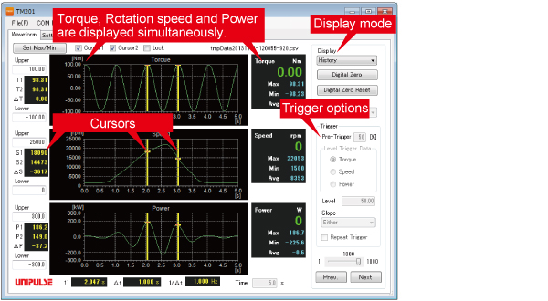
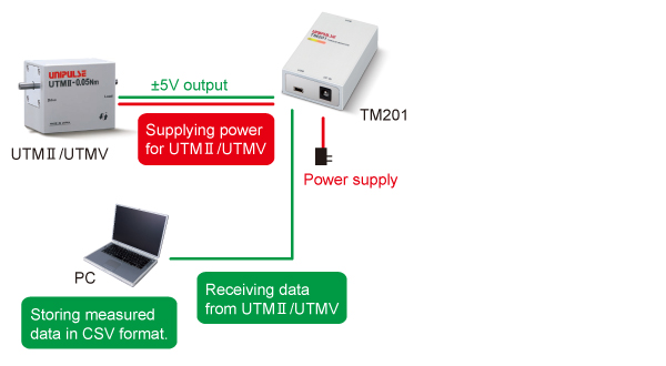
・ Display real-time data sent from UTMⅡ/UTMV via USB0.
・ Torque, rotation speed, power and time in the graph can be specified by cross-lines.
・ Measurement(numeric) data is automatically saved in CSV format.
・ Easy calibration with simple selection of sensor types and display conditions!

■ Display mode
[Normal]
In-progress waveform data will be displayed.
Maximum, minimum, and average value of the waveform data will be displayed.
1. Single
After “start” button is pressed, data will be recorded once for pre-set time period.
2. Continuous
“Single” mode operation will be repeated in cycle until “stop” button is pressed.
3. Level trigger
After “start” button is pressed, it will be put on standby for a trigger.It starts to import the data when the input level goes over the trigger level.
[History]
Previous waveform data can be displayed (up to 1000 files of waveform data can be saved).
■ Trigger options
・Pre-trigger ・Level trigger data ・Trigger level
・Trigger slope ・Repeating trigger
■ Cursors (max.: two)
Torque readings at cursor positions and difference between those two readings will be displayed.

* PC and special software are required to use the TM201.
Application software for the USB interface option can be downloaded from this page.
Torque sensor input|Pulse input for rpm|Power supply for UTMⅡ/UTMV|Display section|Interface|General performance|Attachments
| Torque sensor input (voltage input) | |
| Signal input range | -5 to +5V Input impedance : 1MΩ or more |
|---|---|
| Accuracy |
Non-linearity : Within 0.02%FS±1digit Zero drift : Within 0.2mV/℃ RTI Gain drift : Within 0.01%/℃ |
| Analog filter | Primary low-pass filter 1kHz (fixed) |
| Digital filter | Secondary low-pass filter fc = 3, 30, 300, OFF (variable) |
| Data output rate |
300 times/sec. Resolution : 24bit (binary) Approx. 1/30000 with respect to 5V |
| Pulse input for rpm (input for open collector type) | |
| Maximum input frequency | Compatible with the pulse output frequency of UTMⅡ/UTMV series |
|---|---|
| Minimum input frequency |
Select from 15, 10, 5, 3, or 2 rpm (when pulse rate is 4 ppr) Select from 60, 40, 20, 12, 8 rpm (when pulse rate is 1 ppr) |
| Minimum pulse width | 50μs |
| Circuit layout |
No-voltage (dry) contact input (minus common): open collector outputs can be connected (Ic= approx. 10mA) |
| Power supply for UTMⅡ/UTMV | |
| Power supply | DC24V (UTMⅡ/UTMV 1 unit) |
|---|---|
| Display section | |
| LED status light |
LED (Red) : power supply/alarm status LED (Green) : UTMⅡ/UTMV is operating normally |
|---|---|
| Interface | |
| Interface | USB |
|---|---|
| General performance | |
| Power supply |
AC100V to 240V (+10%-15%) (free power source 50/60Hz) * When supplied AC adapter is used. |
|---|---|
| Power consumption | 4W typ (AC adapter) |
| Operating |
Temperature : Operation 0℃ to +40℃ Storage -10℃ to +60℃ Humidity : 80%RH or less (non-condensing) |
| Dimensions | 50(W)×23(H)×80(D) mm (Projections excluded) |
| Weight | Approx. 120g |
| CE marking certification |
EMC directives EN61326-1 Safety standard EN62311 Please specify requirement for CE marking certified product when making your order. |
| Attachments | |
|
Setup guide ×1 AC adapter for TM201 1.8m ×1 Cable for UTMⅡ/UTMV connection 2m ×1 MiniUSB -USB cable 1.8m ×1 |
|
| Model | Description |
| CA81-USB | miniUSB-computer USB cable 1.8m |
|---|---|
| CATM21-M | 2m cable for connecting UTMⅡ/UTMV |
| CATM51-M | 5m cable for connecting UTMⅡ/UTMV |
| CN90 | Waterproof plastic connector for UTMⅡ/UTMV |
| TM201 AC PIN | AC adapter(JAPAN AC PIN) |
| TM201 AC PIN EU | Switching AC PIN(EU) |
■ About download data
Guide :
TM201 setup guide enclosed at the time of shipment.
Manual :
TM201 operation manual.
USB_setting :
Setting for smooth waveform display. (If smooth waveform display is not required, this setting is not necessary.)
|
Product catalogue(PDF)
|
TM201 catalogue(515 KB) | |
|---|---|---|
 Malaysia