Deskripsi
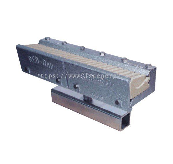
Red-Ray Model F Gas Burners
Used in a wide range of industrial applications such as battery manufacturing, pre-drying, paint flow coating, resin curing, and roofing.
The F series is also used in a wide range of industrial applications such as battery manufacturing, predryers, paint flow coaters, resin curing, roofing materials, etc. Its available in 12” and 7” sizes to allow customer-specified burner assembly lengths for optimum product coverage.
This type of burner employs an air-gas mixture impinging directly on the finned refractory surface to produce a high-density flux of maximum radiance. The flame itself is not the source of infrared radiation. Its function is to heat the refractory to temperatures of 1650° to 2000°F. The refractory then emits infrared energy in the micron range most efficient for the product heating process.
Performance
4,000 Btu/in. at 6 1/2″ w.c. mixture pressure
Develops Radiant Temperatures to 2000°F with Turndown Ratio of 4 to 1
Model F and KN Maintenance and Rebuild Information
-
Inspect refractories on a regular basis and replace if cracked. Why? Cracked refractories can allow direct flame impingement on the cast iron body of the burner. This will greatly reduce burner life and could lead to costly repairs.
-
Always wire brush spacers and their mating castings when replacing burner section components. Don’t hammer them out to attempt to straighten them, but replace them if they are distorted. The rule of thumb for this low cost component which plays such a critical role in burner performance is “When in doubt, change them out.” Why? Clean and non-distorted spacers maintain the consistent orifice critical to proper flame distribution and burner performance.
-
When rebuilding a Red-Ray type F or FH model burner, make sure to position the baffleplate as forward towards the refractory as possible before tightening the baffle plate bolts or screws. Why? This helps to ensure that the orifice created when assembled will have minimal restrictions.
-
Make sure refractories are seated flush to the base plate and tube combination part when rebuilding Red-Ray type KN, F and FH model burners. Why? Poor fitting refractories may create non-uniform heat distribution. If refractories will not seat flush, the base plate and tube combination part probably needs replacing.
-
When rebuilding type F or KN burners, the best practice is to remove all burner sections from manifold for rebuilding or replacing. Why? Replacing only some burner sections may create weaker output on older sections as they may have slightly clogged orifices.
-
Flames exiting refractories should be minimal for optimum burner efficiency on Red-Ray type F and KN burners. Why? Flames longer than 1/2″-1″ exiting the refractories indicate one or more of the following conditions:
-
Improper Air/Gas Ratio – Solution: Make adjustments to butterfly valve (air) and/or mixer (gas).
-
Excessive Air/Gas Volume on Correct Ratio – Solution: Reduce by adjusting the butterfly valve (air) and/or mixer (gas).
-
Deterioration of refractory and/or burner section – Solution: Remove burner section, inspect parts and clean, rebuild or replace as needed.
-
For optimum process performance and burner efficiency Red-Ray type F and KN burners should be rebuilt or replaced when dark spots become numerous. Why? Dark spots along the radiating refractories indicate areas of blockage or warpage in the orifice or other physical conditions which leads to less efficient combustion and over firing of the immediate adjacent areas of the burner.
Features and Benefits
-
Finned cordierite ceramic refractory emitters
-
Input fuel is converted to 30% infrared, 70% convective energy
-
Stainless steel spacer (slit orifice) to deliver an even air/gas mixture
-
High temperature, corrosion resistant alloy side plates
-
Machined cast iron body
-
Modular burner sections with carbon steel orifice union connectors
-
Replaceable ceramic refractory emitters
-
Radiant heat is distributed uniformly
-
High velocity radiant heat diffuses surfaces boundary layers on product process
-
No ported holes to clog
-
Longer wear resistance no dark areas on refractories
-
Less warping, increased burner longevity
-
Structural integrity in continuously operating ovens
-
Quick and easy replacement of burner sections with uniform firing rate across entire burner length
-
Lower stress design and cost effective maintenance
Lihat detail lebih lanjut tentang LSA Energy Resources Sdn Bhd


