Deskripsi
CMM Bridge Benchmark (Half-Gantry type CNC coordinate measuring machine)
Coordinate measuring machine CNC with aluminium alloy mobile half-gantry structure on granite table machine base.
Suface Plate: ganite table with integrated guide-ways with flatness to DIN876/III AND M8 threaded insert grid.
CMM basement
Benchmark: STD CMM Basement
Option: CNC controller & PC integrated
Guideways
X axis machined into granite table (left) and micromachined and hard anodized alloy extrusions (right).
Y axis micro-machied and hard anodized alloy extrusions
Z axis micro-machined and hard anodized alloy extrusions.
Drive method : NC drive via DC motors with zero hysteresis friction drive on steel bar to all axes
Bearing system: Air bearings to all axes
Measuring system: High resolution (0.1um) free floating linear scales mounted in carriers
Motion Control: DC servomotor on all axes
Counterbalance: adjustable pneumatic on Z ram
Thermal compensation: multi-sensors temperature compensation system (total 4 sensors) in option.
Option:
Active vibration insulating system
Multi-wire cable
Power supply
Power supply voltage:
230V + 10%; 50Hz + 2% single phase
115V + 10%, 60 Hz + 2% single phase
Air Supply
Air consumption : (90 NI/min)
Minimum air supply : 5 Bar (71PSI)
Probing system
Manual Probe Head: TPC3, MIH,MH20,MH20i,MH8,RTP20
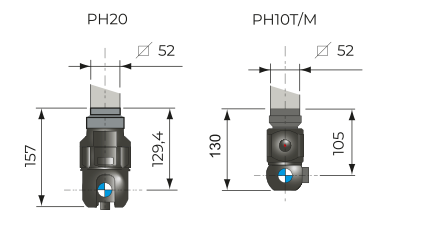
Motorized Probe Head: PH10T,PH10M,PH20
Point-to-point Triggere Probe: TP20,TP200,TP200B
Stylus and probe charges: Fully automated stylus and probe changers
Environment
Temperature Range for Metrological Specification :
Ambient temperature range: 28/22'c
Max.gradient for hour:0.5' K/h
Max.gradient for day: 2.0'K/24h
Max.gradient in space: 0.5' K/m
Operation temperature: 15/35'C
Relative Humidity: 40/80% (non-condensing)
Acceptable Vibrations (Vibration acceleration between peaks):
30mm/s2 from 1 to 10Hz
15mm/s2 from 10 to 20Hz
50mm/s2 from 20 to 100Hz
Benchmark is also available w/o intergrated controleer and mobile arm. Need a unitable desk (1200x800x715mm) for controller and PC/Monitor/keyboard.


|
Model |
Measuring Strokes |
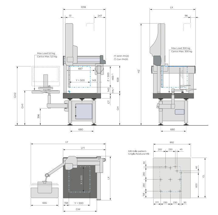
Overall Dimensions |
Surface plate |
Weights |
|
X |
Y |
Z (a) |
LX |
LY |
LY1 (c) |
HZ |
GH |
GT |
GL |
GW |
GH1 |
GH2 |
Max Part Weight |
Machine Weight |
|
|
[mm] |
[mm] |
[mm] |
kg |
|
06.05.05 |
600 |
500 |
500 |
1066 |
1800/1930 |
1018 |
2392 |
750 |
100 |
960 |
803 |
800/1200 |
1395/1825 |
300 |
435 |
a) With PH20 Probe Head Z Measuring stroke will be reduced to 470 mm
b) Weigh includes CMM,Basement. Weight does not include Control and PC, keyboard and Video Terminal (approx.20kg)
c) Benchmark w/o integrated control and articulated arm- need a unitable desk for controller and PC
Specification:
|
Models |
Specification according to UNI EN ISO 10360-2:2O1O |
Max.3D Pos. Speed [mm/s] |
Max.3D Acc [mm/s2] |
|
MOTORIZED |
|
MH20i/PH10T/M/PH20-TP20 |
PH10T/M-TP200 |
|
(1) MPE E0/150 |
(2)MPL R0 |
(1) MPE E0/150 |
(2) MPL R0 |
|
06.05.05 |
2,7 + 3,0 L/1000 |
2,5 |
2,5 + 3,0 L /1000 |
2,5 |
500 |
1500 |
Performace data are only valid if the following specifications are met:
-
MPEeo/MPE(PFTU)/MPLro: PH10M/PH10T/PH20/TP20/TP200: Tip diameter 0 4mm, stylus length 10mm.
-
MPE e150: PH10M/TP20/TP200: tip diameter 0 4mm, stlus lenght 40mm. PH20/MH20i: EM1 STDF, tip diameter 0 4 mm, stylus lenght 20mm. PH10T:PEL2, tip diameter 04 mm, stylus length 10mm
-
L = measuring lenght in mm
-
Ambient temperature range: T1:18/22'C ; Max Gradients: 1,0'c/h-2,0'c/24h-1,0'c/m
-
(1) Maximum permissible error of indication for size measurement according UNI EN ISO 10360-2:2010
-
(2) Maximum permissible shape error with single stylus according UNI EN ISO 10360-5:2010
Performance Verification
MPEeo: Maximum permissible error on lenght measurement with standard probe OFFSET
Measurement of a set of 5 sizes, taken through two opposite probing points on two nominally parallel planes. the sizes are positioned with direction on the 4 volume diagnols and in 3 different positions chosen by the customer (or along the axes according to the standard) in the measurement volume. Each size is measured 3 times for a total of 105 measurements. All 105 measurements (100%) must be within the specified MPEeo.
MPEe150: Maximum Permissible Error on length measurement with probe OFFSET 150mm
Measurement of 1 set of 5 different sizes in 2 diagonal positions on the XZ or YZ plane with a probe OFFSET of 150mm. All 30 measurements must be less than the maximum permissible error MPE E150.
MPLr0 : Maximum Permissible Repeatability Limit
Evaluation of the 35 repeatabiliy values calculated from the difference between the maximum and minimum values of the three differents measurements made on the same length size on each of the 5 samples in each of the 7 positions. Each of these 35 R0 value must be less than the maximum permissible limit MPLR0.
MPE(PFTU): Maximum permissible single stylus form error
A reference sphere is measured with 25 equally distributed probings, estimate of the deviation in the shape of the sphere, obtained as a dispersion band of the 25 polar rays. The probing perfomance shall be verified in one position, placed in the middle of the CMM measure volume. Calculation of the gaussian sphere using the 25 measures. Calculation of the radial distances R, for each of the 25 measured points.Calculation of the PFTU point gripping error, as dispersion band of the 25 radial distances, Rmax-Rmin. The PFTU error must be within the MPE(PFTU).
Lihat detail lebih lanjut tentang Redmark Industry Sdn Bhd


 Malaysia