High-quality, longlife (up to six years) O2 and CO sensors; further sensors (i.e. NO sensor) optional
4-year warranty on the flue gas analyzer
No need to withdraw the sensor from the flue to zero
CO measurements up to 30 000 ppm
The intelligent professional analysis tool for all measurements in and around heating systems. The TÜV-tested testo 330-2 LL flue gas analyzer comes with a wide range of user-changeable, longlife sensors that last for up to six years. Saves you from having to buy an extra measuring device – and new sensors. Product Description
The TÜV-tested testo 330-2 LL flue gas analyzer ensures that you have the proper tools for proper measurements for a proper long time! The easy-to-use, state-of-the-art analysis tool provides you with quick and reliable readings and is built to last for years to come.
4-year warranty on the flue gas analyzer
Bigger savings with longlife (LL) sensors. Because the O2 and CO sensors need to be replaced less often (typically once every six years and therefore once less) you save on costs.
Wide range of optional sensors (i.e. NO, COlow, NOlow sensors) that allow you to customize your analysis tool to suit your individual requirements and saves you from having to buy other flue gas meters or analysis tools
Sensor connector for quick `n easy sensor change. All gas circuits can be connected to the analysis tool via a bayonet lock
The testo 330-2 LL pro flue gas analyzer – one tool for a host of measurements
The testo 330-2 LL pro flued gas analyzer is designed to allow you to carry out all standard installation, service and maintenance measurements in and around heating systems with only one device.
Flue gas parameter (CO, O2, temperature) measurements at burners
Draft measurements at heating systems
Pressure measurements at burners (i.e. die pressure, gas flow pressure)
CO ambient air measurements with optional sensor
Gas leak detection and gas pipe inspections with optional sensors
Pressure difference measurements
testo 330-2 LL flue gas analyzer – it’s what’s on the inside that counts
High-quality, longlife O2, CO and NO – O2- and CO sensors included
Sensor connector for quick `n easy sensor change
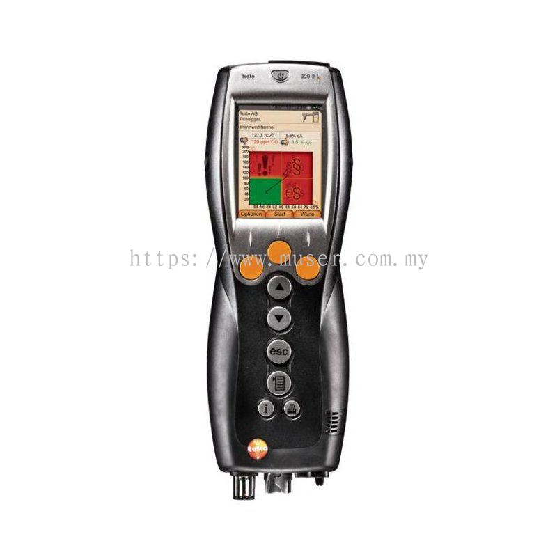
High-resolution graphic color display, graphic presentation of the course of the measurement with flue gas matrix and line diagram
Wide range of measurement menus for heating systems analysis checks
Integrated sensor monitoring; traffic light color coding system and at-a-glance status
No need to withdraw the sensor from the flue to zero (additional feature which the testo 330-1 LL does not have)
CO thinning: automatic thinning from 8 000 ppm to at least 30 000 ppm during CO measurements (another additional feature which the testo 330-1 LL does not have)
Logger function for long-term measurements; supersize memory for up to 500 000 readings
Integrated magnets that stick to almost all metal objects for easy measuring
Easy-to-empty condensate collection tank
Optional Bluetooth interface for optional testo BLUETOOTH® printer
4-year warranty without service contract
TÜV-tested according to 1st BImSchV EN 50379, Parts 1-3
Please Note: If you think that the testo 330-2 LL is just the analysis tool and measuring device you’ve been looking for, but you also need an H2-compensated CO sensor, then you will be pleased to hear that this sensor – and many other optional accessories including a Bluetooth interface – can be ordered together with your flue gas analyzer.
±0.3 Pa (0 to 9.99 Pa) plus ±1 Digit
±3 % of mv (10 to 10000 Pa) plus ±1 Digit
Flue gas O₂
Measuring range
0 to 21 Vol.%
Accuracy
±0.2 Vol.%
Resolution
0.1 Vol.%
Reaction time t₉₀
< 20 s
Flue gas CO (with H₂-compensation)
Measuring range
0 to 8000 ppm
Accuracy
±10 ppm or ±10 % of mv (0 to 200 ppm)
±20 ppm or ±5 % of mv (201 to 2000 ppm)
±10 % of mv (2001 to 8000 ppm)
Resolution
1 ppm
Reaction time t₉₀
< 60 s
Flue gas COlow
Measuring range
0 to 500 ppm
Accuracy
±2 ppm (0 to 39.9 ppm)
±5 % of mv (40 to 500 ppm)
Resolution
0.1 ppm
Reaction time t₉₀
< 40 s
CO determination (with H₂-compensation), automatic dilution
Measuring range
0 to 30000 ppm
Accuracy
±100 ppm (0 to 1000 ppm)
±10 % of mv (1001 to 30000 ppm)
Resolution
1 ppm
Flue gas NO
Measuring range
0 to 3000 ppm
Accuracy
±5 ppm (0 to 100 ppm)
±5 % of mv (101 to 2000 ppm)
±10 % of mv (2001 to 3000 ppm)
Resolution
1 ppm
Reaction time t₉₀
< 30 s
Flue gas Nolow
Measuring range
0 to 300 ppm
Accuracy
±2 ppm (0 to 39.9 ppm)
±5 % of mv (40 to 300 ppm)
Resolution
0.1 ppm
Reaction time t₉₀
< 30 s
Flue gas Draught
Measuring range
-9.99 to +40 hPa
Accuracy
±0.02 hPa or ±5 % of mv (-0.50 to +0.60 hPa)
±0.03 hPa (+0.61 to +3.00 hPa)
±1.5 % of mv (+3.01 to +40.00 hPa)
Resolution
0.01 hPa
Temperature
Measuring range
-40 to +1200 °C
Accuracy
±0.5 °C (0 to +100.0 °C)
±0.5 % of mv (Remaining Range)
Resolution
0.1 °C (-40 to +999.9 °C)
1 °C (> +1000 °C)
Flue gas degree of effectivity, Eta (calculated)
Measuring range
0 to 120 %
Resolution
0.1 %
Flue gas loss (calculated)
Measuring range
0 to 99.9 %
Resolution
0.1 %
Flue gas CO₂ calculation (calculated from O₂)
Measuring range
0 to CO₂ max (Display range)
Accuracy
±0.2 Vol.%
Resolution
0.1 Vol.%
Reaction time t₉₀
< 40 s
Velocity / Volume flow
Measuring range
0.15 to 3 m/s
Resolution
0.1 m/s
Pressure measurement
Measuring range
0 to +300 hPa
Accuracy
±0.5 hPa (0.0 to 50.0 hPa)
±1 % of mv (50.1 to 100.0 hPa)
±1.5 % of mv (Remaining Range)
Resolution
0.1 hPa
Flue gas CO (without H₂-compensation)
Measuring range
0 to 4000 ppm
Accuracy
±20 ppm (0 to 400 ppm)
±5 % of mv (401 to 2000 ppm)
±10 % of mv (2001 to 4000 ppm)
Resolution
1 ppm
Reaction time t₉₀
< 60 s
Ambient CO
Measuring range
0 to 500 ppm
Accuracy
±5 ppm (0 to 100 ppm)
±5 % of mv (> 100 ppm)
Resolution
1 ppm
Reaction time
Approx. 35 s
with CO probe
Ambient CO₂
Measuring range
0 to 1 Vol.%
0 to 10000 ppm
Accuracy
±50 ppm or ±2 % of mv (0 to 5000 ppm)
±100 ppm or ±3 % of mv (5001 to 10000 ppm)
Reaction time
Approx. 35 s
with ambient CO₂probe
Gas leak measurement for combustible gases (via gas leak detection probe)
Measuring range
0 to 10000 ppm CH₄ / C₃H₈; Display range
Accuracy
Signal optical display (LED) audible signal via buzzer
Reaction time t₉₀
< 2 s
with gas leak detection probe
Temperature (via the fine pressure probe)
Measuring range
-40 to +1200 °C max. (dependent on probe)
Accuracy
±0.5 °C (-40 to 100 °C)
±0.5 % of mv (Remaining Range) plus probe accuracy
Resolution
0.1 °C
General technical data
Dimensions
270 x 90 x 65 mm
Operating temperature
-5 to +45 °C
Display size
240 x 320 pixels
Display function
Colour graphic display
Power supply
Rechargeable battery pack 3.7 V / 2.6 Ah; Mains unit 6 V / 1.2 A
Maximum memory
500,000 readings
Storage temperature
-20 to +50 °C
Weight
600 g (without rechargeable battery)
Application
Ambient CO measurement in the heated environment
Carbon monoxide (CO) is a colourless, odourless and taste-free gas, but also poisonous. It is produced during the incomplete combustion of substances containing carbon (oil, gas, and solid fuels, etc.). If CO manages to get into the bloodstream through the lungs, it combines with haemoglobin thus preventing oxygen from being transported in the blood; this in turn will result in death through suffocation. This is why it is necessary to regularly check CO emissions at the combustion points of heating systems and the surroundings. Measuring pressure on burners (nozzle pressure, gas flow pressure, etc.)
Standard readings taken during services of domestic heating systems include checking the gas pressure on the burners. This involves measuring the gas flow pressure and gas resting pressure. The flow pressure, also called supplied pressure, refers to the gas pressure of the flowing gas and resting pressure of the static gas. If the flow pressure for gas boilers is slightly outside the 18 to 25 mbar range, adjustments must not be made and the boiler must not be put into operation. If put into operation nonetheless, the burner will not be able to function properly, and explosions will occur when setting the flame and ultimately malfunctions; the burner will therefore fail and the heating system will shut down.
Measuring the flue gas parameters of the burner (CO, O2, and temperature, etc.)
The flue gas measurement for a heating system helps to establish the pollutants released with the flue gas (e.g. carbon monoxide CO or carbon dioxide CO2) and the heating energy lost with the warm flue gas. In some countries, flue gas measurement is a legal requirement. It primarily has two objectives:
Ensuring the atmosphere is contaminated as little as possible by pollutants; and
energy is used as efficiently as possible.
Stipulated pollutant quantities per flue gas volume and energy losses must never be exceeded.
Measurement in terms of results required by law takes place during standard operation (every performance primarily using the appliance). Using a Lambda probe (single hole or multi-hole probe), the measurement is taken at the centre of flow in the connecting pipe (in the centre of the pipe cross-section, not at the edge) between the boiler and chimney/flue. The measured values are recorded by the flue gas analyzer and can be logged either for print out or transfer to a PC at a later stage.
Measurement is taken by the installer at commissioning, and if necessary four weeks later by the flue gas inspector/chimney sweep, and then at regular intervals by the authorised service engineer.
Measuring temperatures on radiators
When measuring temperatures on radiators, the flow and return temperature are recorded in particular and assessed by the tradesman. The flow temperature is defined as the temperature of the thermal transfer medium (e.g. water) that the system is supplied with. The temperature of the medium flowing out of the system is accordingly called the return temperature. To prevent losses within the heat distribution system and achieve a better level of efficiency spot recording of flow and return temperatures are necessary. Implementation of relevant measures ultimately leads to hydraulic adjustment on the basis of knowledge about the flow and return temperatures. This defines a procedure with which every radiator or heating circuit of a flat radiator within a heating system is supplied at a set flow temperature with the precise amount of heat needed to achieve the ambient temperature required for the individual rooms. Flawed operating conditions will result in considerable excess consumption of electricity and heating energy. The German Energy Saving Regulation (EnEV) therefore requires hydraulic adjustment for systems being set up or overhauled for this very reason.
Muser Apac Sdn BhdTesting Instruments Supplier Kuala Lumpur (KL), Malaysia, Monitoring Mapping Systems Supply Selangor, Measuring Equipments Supplies ~ Muser Apac Sdn Bhd
 Malaysia