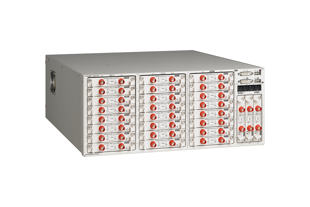
HIOKI MR8740 MEMORY HiCORDER
Single-device Solution for Waveform Recording and Generation, High-speed 54-channel/Isolated Multi-channel System Recorders (rack-mounted)
The MR8740 is rack-mountable data acquisition system that delivers high-speed, multi-channel measurements over maximum of 32+22 channels. The MR8990 DVM module is a 2-channel input unit for the MR8740 for measuring minute fluctuations in output from sensors in automobiles and other equipment and voltage fluctuations in devices such as batteries at high levels of precision and resolution.
Use with the Arbitrary Waveform Generator Unit U8793 to create a function generator, arbitrary waveform generator, and waveform measurement in a single device.

| Max. Number of channels | [Block I] 32 ch analog + 8 ch logic, or 29 ch analog + 56 ch logic (when used with built-in logic input + plug-in logic unit 8973 × 3) [Block II] 22 ch analog + 8 ch logic, or 19 ch analog + 56 ch logic (when used with built-in logic input + plug-in logic unit 8973 × 3) |
|---|---|
| Number of slots | [Block I] 16 slots (Max. 16) [Block II] 11 slots (Max. 11) [Limitation on number of slots] when using the Current Unit 8971: Max. 4, When using the Logic Unit 8973: [Block I] Max. 3; cannot use slots 9 to 16 [Block II] Max. 3; cannot use slots 9 to 11 |
| Number of logic channels | [Block I] 8 ch logic (Logic probe terminal GND share a common GND with chassis. ) [Block II] 8 ch logic (Logic probe terminal GND share a common GND with chassis. ) [Limitation on using built-in logic input] applies to both Block I and Block II (with logic measurement ON) - Measurement resolution on slots 1 and 2 is limited up to 12 bits - Cannot use Frequency Unit 8970 on slots 1 and 2 - When using the DVM Unit MR8990 on slots 1 or 2: cannot use built-in logic input |
| Measurement ranges (20 div full scale) | 5 mV to 20 V/div, 12 ranges, resolution : 1/100 of range (when using 8966) 5 mV to 50 V/div, 5 ranges, resolution : 1/50,000 of range (when using MR8990) |
| Max. allowable input | 400 V DC (when using 8966; upper limit voltage that can be applied between input terminals without damage) |
| Max. rated voltage to earth | 300 V AC/DC (input and instrument are isolated; between input channels and chassis; upper limit voltage that can be applied between input channels without damage) |
| Frequency characteristics | DC to 5 MHz (-3 dB, when using 8966) |
| Time axis (MEMORY operation) | 5 µs to 5 min/div; 26 ranges; time axis resolution: 100 points/div; time axis expansion: 3 stages from ×2 to ×10; compression: 13 stages from 1/2 to 1/20,000 |
| Measurement functions | Memory (high-speed recording), FFT |
| Memory capacity | 16 MW/ch (fixed), total of 864 MW installed |
| Removable storage | USB memory stick (USB 2.0) |
| Display | None (1 digital DVI terminal per block, 800 × 600 dots) |
| External interfaces | [LAN] 100Base-TX (DHCP and DNS support, FTP server, HTTP server) [USB] USB 2.0 Series A receptacle × 2 (mouse operation) |
| Power supply | 100 to 240 V AC, 50/60 Hz (250 VA max.) |
| Dimensions and mass | 426 mm (16.77 in) W × 177 mm (6.97 in) H × 505 mm (19.88 in) D, 10.8 kg (381.0 oz) (main unit only) |
| Included accessories | Instruction manual × 1, Application disk (Wave viewer Wv, Communication commands table) × 1, Power cord × 1 |
 Malaysia