ATOS 5 for Airfoil

ATOS 5 for Airfoil

Category: High Precision 3D Metrology Available
For more information, visit our official website at 1st.com.my

Description

Tailor-made for turbine industry

Precision and quality of the smallest details

Developed for gas turbine industries, ATOS 5 for Airfoil with its optimized working distance and measuring areas from 100 x 70 mm² delivers high-precision 3D data of the smallest details in a short measuring time.


Airfoil Inspection Features

The GOM software has a complete set of airfoil inspection functionalities. The inspection principles include standard and customizable options to meet different engineering standards and types of airfoil drawings. The user-defined inspection principle (UDIP) enables fast, standardized and efficient inspections of airfoil sections.
 

Surface Comparison

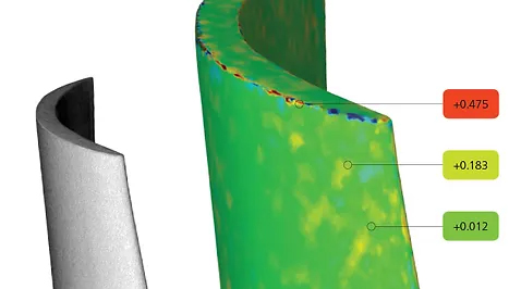
A 3D representation of surface deviations to the CAD or master mesh is standard in GOM technology. Surface comparisons are typically used when developing new products to search for issues in the manufacturing process. Comparisons can be made in multiple alignments including best-fit to CAD or RPS. This powerful tool reveals product details that traditional tools cannot provide.

Edge Points and Edge Circles

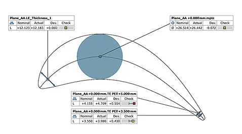
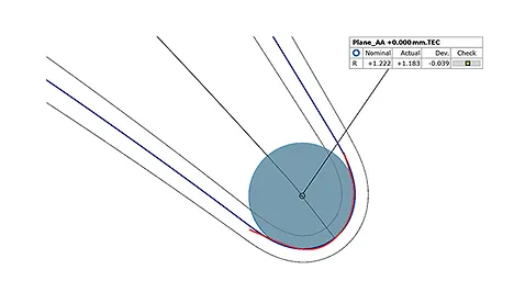
Edge point creation is a standard functionality and determined by the pierce point of the camber line at the leading or trailing edge with the suction and pressure side of the airfoil. Expert parameters allow moving points along the camber line. Edge circles are also automatic and generate elements at the leading or trailing edge of the airfoil.


Thicknesses

Standard functionality that creates thicknesses at the leading or trailing edge of the airfoil. The simple dialog prompts a distance value at which the thickness is to be taken from the edge point. Different options allow the measurement to be traced along the camber line. Traditional thicknesses at predefined drawing angles can also be created. A maximum airfoil thickness check is also available using the distance or maximum inscribed circle method.

Form and Position Checks

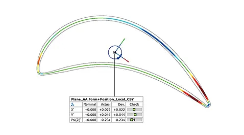
The software enables a flexible way to evaluate form and position of airfoil sections to meet end-user needs. Evaluation techniques of the actual section data can be compared using Chebyshev, Gaussian or best-fit by tolerance methods. The software can also compare the results with changing tolerance regions where tolerances are different across areas of the airfoil sections.

More detail about FIRST METROLOGY SDN BHD
FIRST METROLOGY SDN BHD
FIRST METROLOGY SDN BHD 3D Scanning & Inspection Malaysia, Optical Measurement Supplier Selangor, Industrial Metrology Solutions KL ~ FIRST METROLOGY SDN BHD
Contact Us flagMalaysia