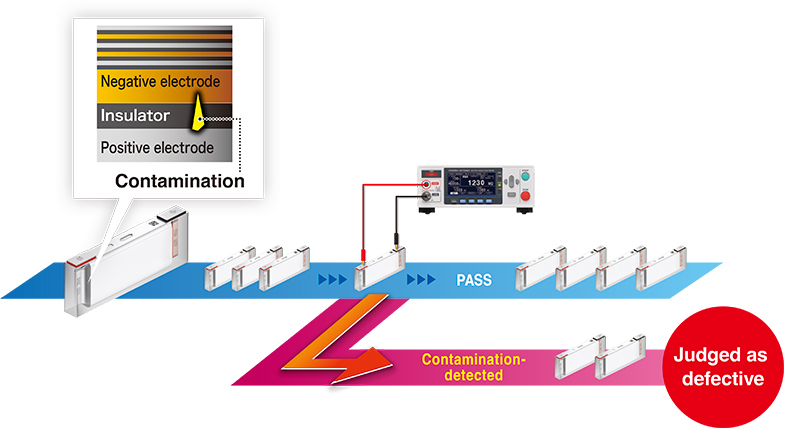
The BDD function is a proprietary testing function that can detect minuscule internal short-circuits caused by contamination (with metallic matter) at the stage before battery cells are filled with electrolyte. By identifying and eliminating defective parts at an early stage in the production process, the BDD function helps prevent the risk of hazards such as fires and accidents caused by heating after battery shipment. In addition, minuscule internal short-circuits in cells accelerate battery degradation. The BDD function will contribute to the production of batteries with greater durability and electrical performance.
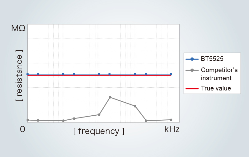
Hioki succeeded in significantly reducing the effects of external noise by drawing on insulation resistance tester measurement technology and design expertise cultivated over many years.
As a result, the BT5525 can perform stable, variation-free insulation resistance testing at a level of quality that lets its detect internal short-circuits caused by contamination.
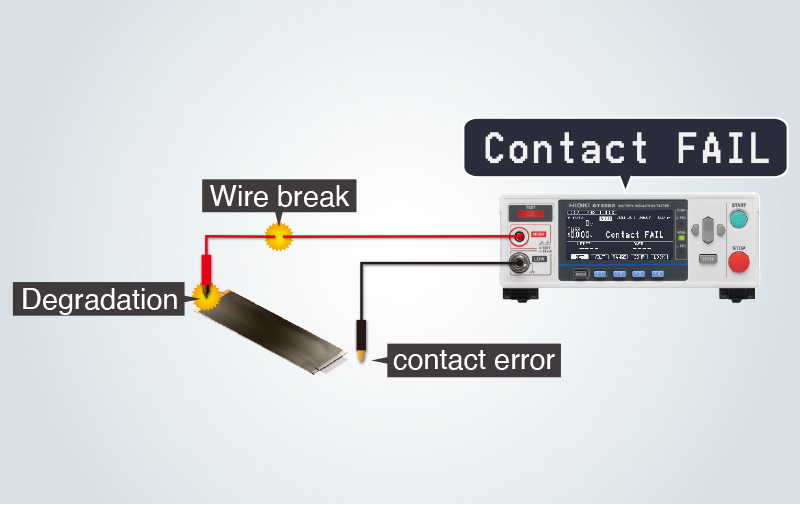
The BT5525 provides a contact check function to determine whether the instrument has made proper contact with the circuit under test by measuring the capacitance between the measurement terminals (stray capacitance and the capacitance of the circuit under test).
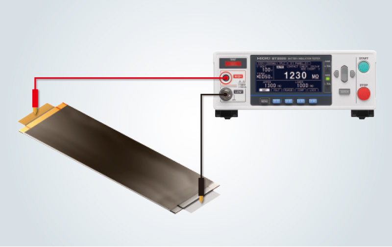
The BT5525 tests insulation between electrodes before cells are filled with electrolyte. Its maximum test voltage is 500 V. If certain test conditions are satisfied, it can also perform insulation testing between module/pack electrodes and the enclosure.
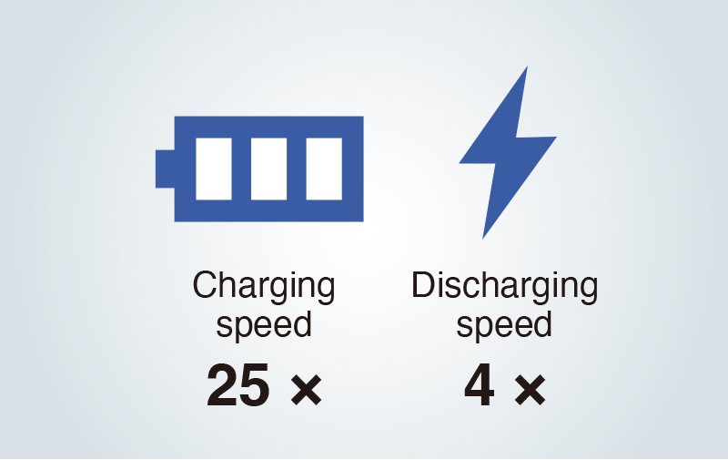
The BT5525 features high-speed charging at up to 50 mA and high-speed discharging of residual charge at 40 mA. The instrument’s dramatically improved charging and discharging performance boosts testing speed, accelerating charging by about 25 times compared to previous models, and discharging by about 4 times. In this way, it can shorten insulation resistance testing times for batteries, which manufacturers are producing at ever-higher levels of capacity.
*Compared to Hioki’s INSULATION TESTER ST5520.
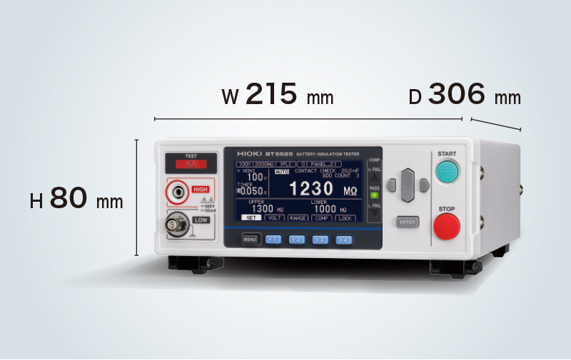
Drawing on many years of expertise in product design, Hioki has delivered high performance in a compact package. The instrument can be embedded in testing systems, allowing their size to be reduced. Manufacturers can deploy compact testing systems to make the most of limited production space.
The BT5525's functionality and performance make it a cost-effective solution due to careful consideration given to the demands of battery insulation resistance testing. Fluctuations in voltage and current during insulation resistance testing can be viewed using a dedicated PC application.
The instrument can output a test voltage of up to 500 V. The instrument satisfies insulation resistance testing conditions for everything from the large batteries used in electric vehicles (EVs) to small battery cells.
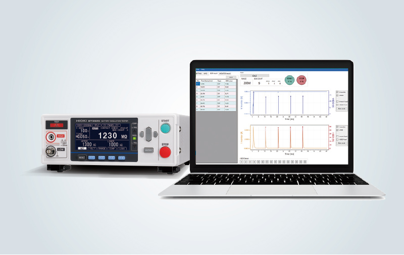
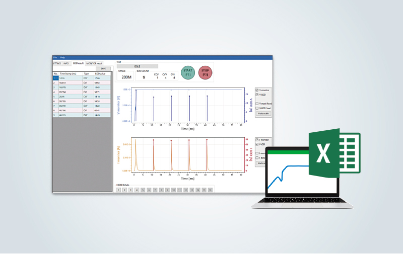
A free PC application from Hioki can be used to review fluctuations in voltage and current.
The ability to review waveforms can be useful when analyzing test results and when determining judgment reference values for testing lines.
Since data can be output in the CSV format, waveforms can also be reviewed in other applications, for example Excel.
| Main functions | Insulation resistance test Break Down Detect function (BDD) Contact check function |
|---|---|
| Output specifications | Output voltage : 25 V to 500 V, Setting resolution 1 V Charging current (Current limit function) : 50 µA to 50 mA*1*2*3, Minimum setting resolution 10 μA Short-circuit current : 60 mA or less Discharge current : 40 mA or greater *1: Constraints involving the output generator will result in an error, making measurement impossible, if a capacitive load of approximately 50 μF or greater is connected while using a current limit setting of 5.1 mA or greater. *2: When using a current limit setting of 5.1 mA or greater, measurement will be forcibly stopped if the output voltage is not at least 20 V at 200 ms after the start of measurement. Measurement will be possible 1 s after forcibly stopped. *3: If the set current limit value is from 5.1 mA to 50.0 mA, the current will be limited to 5 mA after the output voltage reaches the set voltage. |
| Measurement specifications | Resistance value display range : 0.050 M!& to 9999 M!& Resistance range : 2 M!&, 20 M!&, 200 M!&, 2000 M!&, AUTO |
| Basic specifications | ±1.5% rdg.±2 dgt. 25 V ≤ V < 100 V [0.05 MΩ to 2 MΩ], 100 V ≤ V ≤ 500 V [0.2 MΩ to 20 MΩ] |
| Time specifications | Test time : 0.050 s to 999.999 s, OFF Comparator delay time : 0.001 s to 999.999 s, AUTO Display update speed : 1 PLC Sampling time : 1 PLC to 100 PLC |
| Memory functions | Panel save function : Saves up to 15 sets of measurement conditions Measured value memory function : Saves up to 999 measured values in the instrument's internal memory |
| Judgment functions | Test modes : Continuous test, PASS STOP, FAIL STOP Comparator function : UPPER_FAIL : Measured value > upper limit value PASS : Upper limit value ≥ measured value ≥ lower limit value LOWER_FAIL : Measured value < lower limit value |
| Various functions | Break Down Detect function (BDD) : Detecting minuscule insulation defects caused by contamination Contact check function : 2-terminal capacitance measurement method Automatic data output function : Automatic output of measurement results via communication interface after completion of test Command monitor function : Screen display of commands being sent and received External I/O monitor function : Screen display of output signal ON/OFF and input signal status Analog output function : Converts measured values to 0 to 4 V DC and outputs |
| Interfaces | USB, LAN, RS-232C, EXT. I/O |
| Power supply | 100 V to 240 V AC |
| Power consumption | Approx. 20 VA*4 *4: Power supply conditions are 220 V supply voltage, 50, 60 Hz supply frequency, 200 V test voltage, 2 mA current limit, and load (1 GΩ resistor and 0.1 μF capacitor connected in parallel). |
| Maximum rated power | 100 VA |
| Dimensions and mass | Approx. 215 mm (8.46 in) W × 80 mm (3.15 in) H × 306.5 mm (12.07 in) D (excluding protruding parts), Approx. 2.8 kg (98.8 oz) |
| Included accessories | Power cord ×1, EXT. I/O male connector ×1, EXT. I/O connector cover ×1, EXT. I/O interlock cancellation jig ×1, Startup Guide ×1 |
 Malaysia