Sensor input(Standard)|Sensor input(Multisensor input:MLT)|Analog voltage output|Display section|COMP. & JUDGE. function|Preventive maintenance support|External signal|Interface|General performance|Attachments
| Sensor input | |
| Sensor input for load (Fixed as strain gauge input)(6-wire) | |
| Excitation voltage | DC 2.5, 5, 10V±10% (depending on settings) Output current: Within 30mA |
|---|---|
| Signal input range | -2.0mV/V to +2.0mV/V |
| Accuracy | Non-linearity: Within 0.02%/FS ±1 digit (at 2.0mV/V input) Zero drift: Within 0.1μV/℃ RTI Gain drift: Within 15ppm/℃ |
| Low-pass filter | Selectable from 10 to 10kHz(at A/D converter speed 25000 times/sec) Selectable from 2 to 2kHz(at A/D converter speed 5000 times/sec) |
| A/D converter | Speed: Selectable from 25000 times/sec., 5000 times/sec. Resolution: 24bit (binary) |
| Sensor input for displacement Pulse input(Line driver) |
|
| Max. input frequency | 1MHz |
| Internal count range | Approx. 1,000,000 |
| Adaptable rotary encoder | Output: Incremental type 2-phase output (A/B signal output) Also capable of single-phase output (A-phase input used. All pulses are counted as in the plus direction.) Output stage circuit specification: Line driver (Based on RS-422) |
| Sensor input(Multisensor input:MLT or MLT2) | |
| Sensor input for load (Fixed as strain gauge input)(6-wire) | |
| Excitation voltage | DC 2.5, 5, 10V±10% (depending on settings) Output current: Within 30mA |
|---|---|
| Signal input range | -2.0mV/V to +2.0mV/V |
| Accuracy | Non-linearity: Within 0.02%/FS ±1 digit (at 2.0mV/V input) Zero drift: Within 0.1μV/℃ RTI Gain drift: Within 15ppm/℃ |
| Low-pass filter | Selectable from 10 to 10kHz(at A/D converter speed 25000 times/sec) Selectable from 2 to 2kHz(at A/D converter speed 5000 times/sec) |
| A/D converter | Speed: Selectable from 25000 times/sec., 5000 times/sec. Resolution: 24bit (binary) |
| Sensor input for displacement Pulse input (Open collector)[MLT] |
|
| Max. input frequency | 1MHz |
| Internal count range | Approx. 1,000,000 |
| Adaptable rotary encoder | Output: Incremental type 2-phase output (A/B signal output) Also capable of single-phase output (A-phase input used. All pulses are counted as in the plus direction.) Output stage circuit specification: Open collector (built in pull-up resistor) |
| Sensor input for displacement Pulse input(Line driver)[MLT2] |
|
| Max. input frequency | 1MHz |
| Internal count range | Approx. 1,000,000 |
| Adaptable rotary encoder | Output: Incremental type 2-phase output (A/B signal output) Also capable of single-phase output (A-phase input used. All pulses are counted as in the plus direction.) Output stage circuit specification: Line driver (Based on RS-422) |
| Voltage input | |
| Signal input range | -10 to +10V |
| Input impedance | App. 1MΩ |
| Accuracy | Non-linearity:Within 0.02%/FS ±1 digit (at 10V input) Zero drift:Within 0.2mV/℃ RTI Gain drift:Within 0.01%/℃ |
| Low-pass filter | Selectable from 10 to 10kHz(at A/D converter speed 25000 times/sec) Selectable from 2 to 2kHz(at A/D converter speed 5000 times/sec) |
| A/D converter | Speed:Selectable from 25000 times/sec, 5000 times/sec Resolution:24bit Effective Resolution: Approx. 1/20000 against 10V |
| Analog voltage output | Output level: Approx. 2V per 1.0mV/V input Load resistance: 2kΩ or more |
|---|
| Display section | |
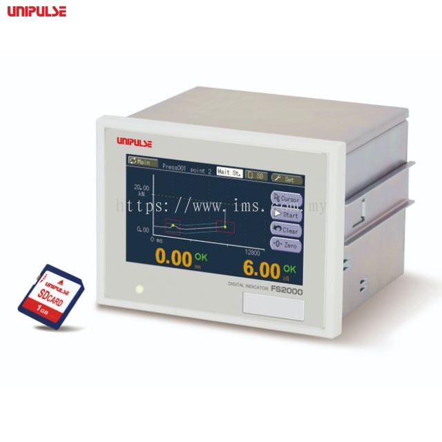
| Display | 4.3 inch TFT color LCD module Display area: 95.0(W)×53.9(H) mm Dot configuration: 480×272 dot |
|---|---|
| Display frequency | Fixed at 3 times/sec. |
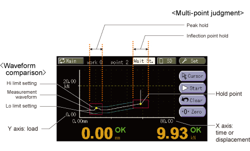
| COMP. & JUDGE. function | |
| Multi point comparison mode 16ch (setting values can be stored) |
Capable of judging up to 5 hold points at the same time. Sample, Peak, Bottom, P-P, Relative Maximum, Relative Minimum, Inflection Point, Average, End |
|---|---|
| Waveform comparison mode 16ch (setting values can be stored) |
Compares the actually measured waveform against the preset Hi/Lo waveforms. The overall measured waveform will be compared against the preset Hi/Lo and if any of its points exceeds the preset waveform, then the measured waveform will be NOK. |
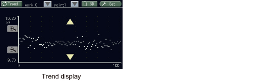
| Preventive maintenance support | |
| Trend display | Showing the trend of measurement data to help finding irregularities at early stage. |
|---|---|
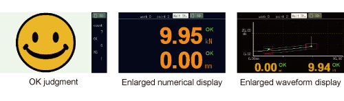
| Statistics | Using the latest 10000 measured data. Displaying number of measurement, OK, NOK |
| Screen capture | Saves screen capture data as bmp data. |
| Work name edit | Work name can be edited and displayed for each Work No.. |
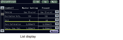
| Setting list display | Changed setting items comparing to master set values are highlighted. |
| User management | Login ID and Password |
| External signal | |
| Output signal | 16 points Hold judgment (load, displacement)/ Load overload/ Measurement complete/ Waveform comparison judgment/ Load & displacement OK/ CPU OK/ SD card OK/ Timing output 1,2 Output Type: Sink type/source type selectable. (Source Type is option: [ISC]) Output transistor ON at signal ON. To connect an input unit like a PLC, connect plus common for sink type, and minus common for source type. Rated voltage: 30V Rated current: 30mA |
|---|---|
| Input signal | 16 points Load digital zero/ Displacement adjustment/ Measurement start/ Measurement end/ HOLD1 to 5/ Reset/ Forcibly light up the backlight/ Touch panel lock/ Work change Input type: Plus common/Minus common selectable. (Minus common is option: [ISC]) To connect a transistor, connect NPN output type (sink type) for plus common and PNP output type (source type) for minus common. |
| Interface Only one option can be installed. |
|
| USB | USB interface |
|---|---|
| ODN | DeviceNet interface (option) |
| CCL | CC-Link interface (option) |
| EIP | EtherNet/IP interface (option) |
| General performance | |
| Power supply voltage | DC24V (±15%) |
|---|---|
| Power consumption | 6W typ |
| Operation condition | Operation temperature: -10℃ to +40℃/ Storage temperature: -20℃ to +60℃ Humidity: 85% RH or less (non-condensing) |
| Dimensions | 132(W)×98(H)×110(D) mm (Projections excluded) |
| Weight | Approx. 1.0kg |
| Attachments | |
| I/O connector (with cover) | 1 |
|---|---|
| Analog connector | 1 |
| Operating tool | 1 |
| SD card | 1 |
| Operation manual | 1 |
| DeviceNet connector (when DeviceNet option is selected) | 1 |
| CC-Link connector (when CC-Link option is selected) | 1 |
| Model | |
| ISC | I/O source board |
|---|---|
| MLT | Multisensor input |
| MLT2 | Multisensor input |
| ODN | DeviceNet interface |
| CCL | CC-Link interface |
| EIP | EtherNet/IP interface |
| Model | |
| CN71 | CC-Link connector |
|---|---|
| CN72 | Double row connector for CC-Link |
| CN77 | Analog connector |
| CND01 | DeviceNet connector |
| SD1G | 1 GByte SD card |
| SD2G | 2 GByte SD card |
| SD16G | 16 GByte SD card |
| SD32G | 32 GByte SD card |
| CA81-USB | USB cable (A-miniB type) 1.8m |
| TSU03 | DC lighting surge unit |
 Malaysia